The RF Performance of the General Radio GR874 Connector
The Golden Low Reflection Standard of the 1950s
Introduction
The GR874 RF connector was conceptualized between 1947 and 1948 by General Radio being popular throughout 1950 up until 1970 for many different pieces of RF equipment. The hermafrodite design as well as its low reflection coefficients and relatively operating frequency (up to 10 GHz) allowed for its popularization. However, its large size and high cost inevetially caused its decline once SMA become popular.
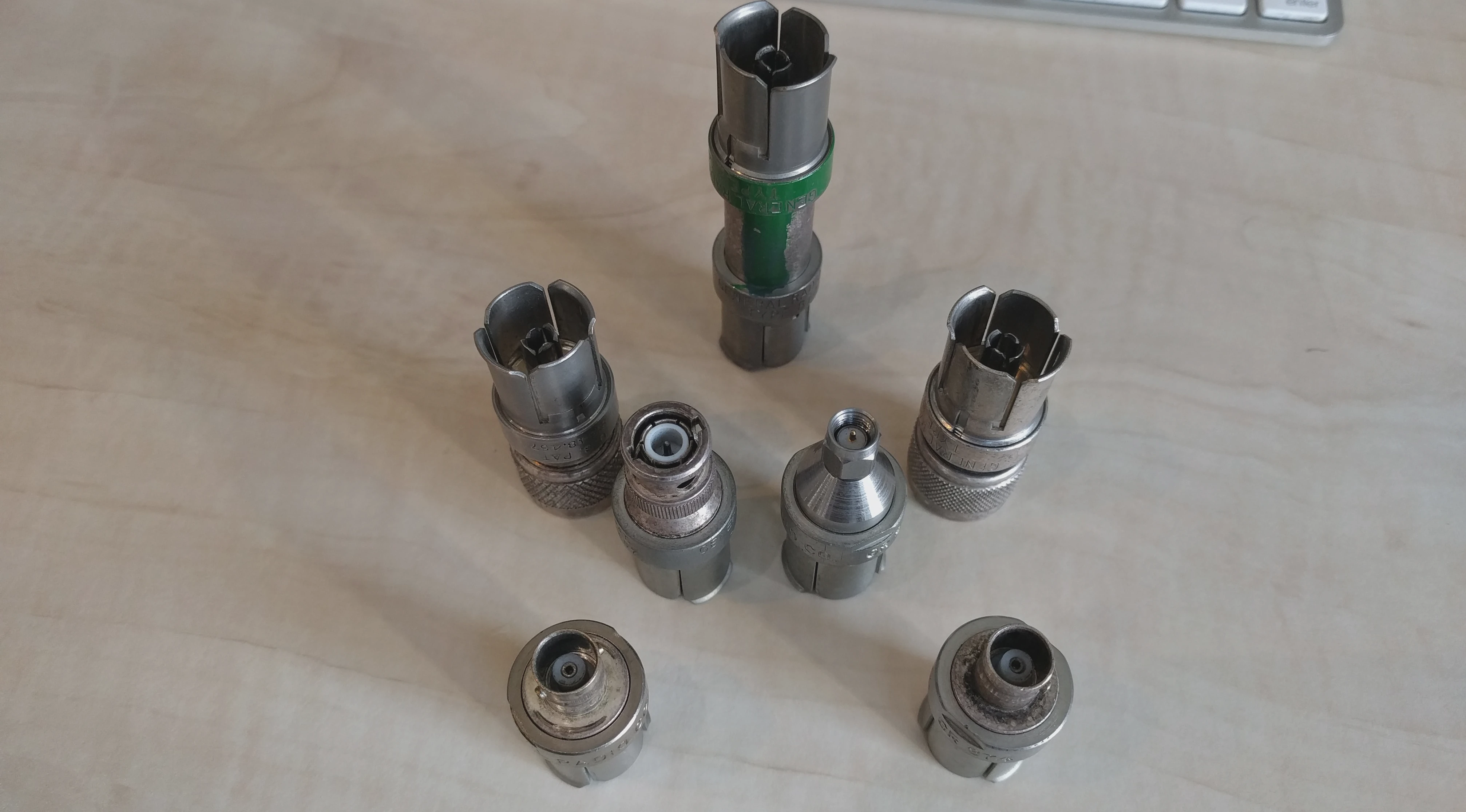 Collection of General Radio GR874 Adapters & Couplers - CC BY-NC-SA 4.0 Corne Lukken (Dantali0n)
These connectors were available in both locking and non locking variants as well as adapters to a large variety of different other RF connectors. Notably, the GR874 system was often used in academic setups with stub filters or air lines. The 1973 brochure of these adapters is readily available online [1].
Given their conception in the early 50s and their popularity up until the late 70s how would these adapters hold up in 2024?
Goal
In this article the LiteVNA is utilized to characterise reflection & attentuation performance of half a dozen adapters and one AC coupler. For this AC coupler the high pass -3 dB cross over point will also be identified.
All these adapters are expected to have excellent SWR (reflection coefficient) and minimal attentuation till far beyond the maximum measurement frequency of 6.3 GHz of the LiteVNA. From the brochure we expect the SWR to be less then 1/1.10 typically although variance and error in the measurement setup will likely prohibit measuring down to such low SWR.
Measurement Setup
The LiteVNA is calibrated from 150 KHz to 6.3 GHz using 1024 measurement points and 20 averages per point. Additionally two adapters from SMA to BNC and BNC to SMA are used respectively. These adapters will fit most GR874 adapters allowing to largely isolate imperfections from the measurement setup. The measurements affected by discrepancies in the setup will be marked explicitely.
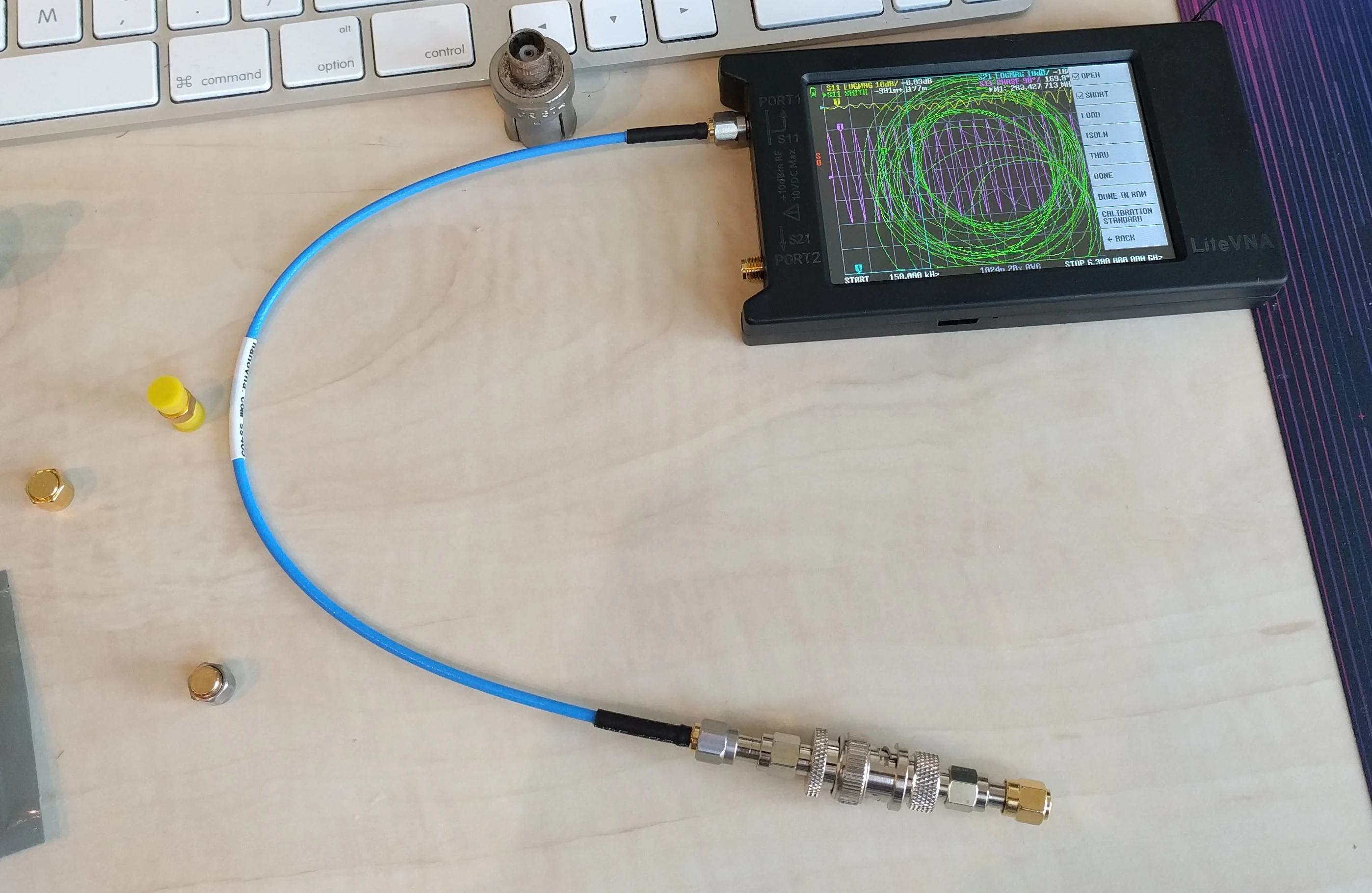 Calibration Setup for the LiteVNA - CC BY-NC-SA 4.0 Corne Lukken (Dantali0n)
Because we have to convert SMA to GR874 and back to SMA for the termination we will effectively always measure two adapters in a single measurement.
Results
The results are separated into two section one for reflection (S11) measurements and one for the attentuation (S21). Lastly, the results for the ac coupler are shown separately.
In total two BNC female, Two N male, one BNC male and one SMA male adapter are measured as well as the ac coupler.
Reflections
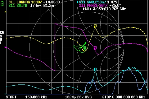
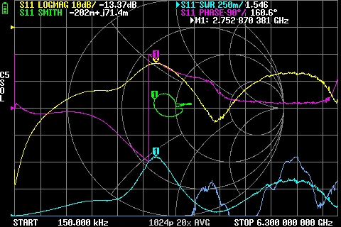 GR874 Reflections BNC male + BNC female adapters
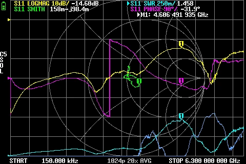
Interestingly enough the second BNC male adapter seemed to have some kind of oxide coating that made the results seem AC coupled. After some brief cleaning this oxide coating and its effects on the results went away. The results without cleaning are shown first followed by when the BNC male adapter was cleaned.
 GR874 Reflections BNC male + BNC female 2nd adapter with oxide
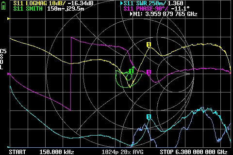
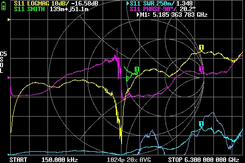
 GR874 Reflections BNC male + BNC female 2nd adapter
 GR874 Reflections BNC male + SMA male adapter
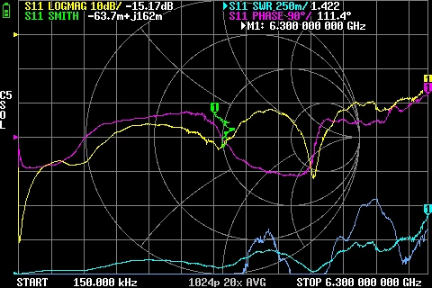
 GR874 Reflections BNC male + N male adapter
 GR874 Reflections BNC male + N male 2nd adapter
Across the board the highest SWR did not go beyond 1/1.6. From the original manufactering specification these adapters do not exceed 1/1.10 all the way up to the 8.5 GHz they are rated for. Given room for measurement error and that each measurement constitutes two adapters back to back it is fair to assume these adapters still perform very close to the original rated reflection coefficients.
Attenuation
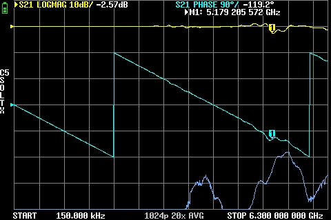 GR874 Attenuation BNC male + BNC female adapters
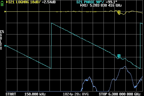 GR874 Attenuation BNC male + BNC female 2nd adapter
Due to shortcomings in the measurement setup, primarily, the absence of the second BNC to SMA adapter the following results will show amplifcation for some frequencies. This amplification is not real as these adapters are passive but rather a result of having lower attentuation then the second BNC to SMA adapter would have introduced.
 GR874 Attenuation BNC male + SMA Male
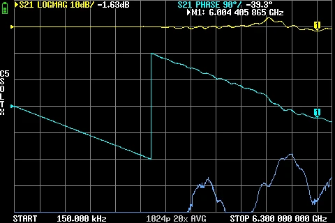
 GR874 Attenuation BNC male + N Male
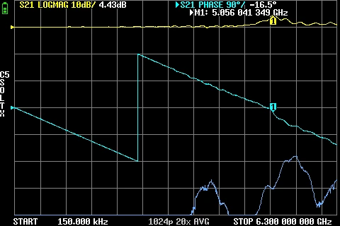
 GR874 Attenuation BNC male + N Male 2nd adapter
AC coupler
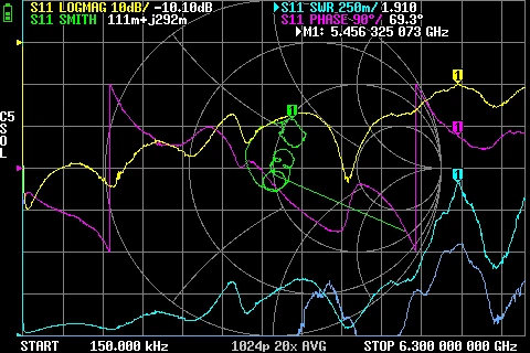 GR874 AC Coupler Reflections BNC male + SMA Male
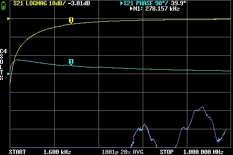 GR874 AC Coupler Attenuation Low Frequency BNC male + SMA Male
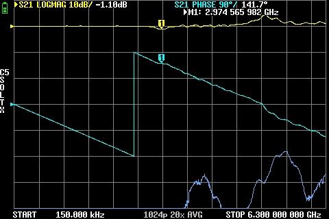
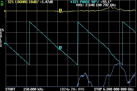 GR874 AC Coupler Attenuation BNC male + SMA Male
Conclusion
These adapters and coupler hold up extremely well for their age. Not only is the -3 dB already reached at just 280 KHz for the AC coupler it performs nearly without any attentuation up till 6.3 GHz.
The higest attentuation was found in the BNC adapters but is close to within measurement error. Similarly reflections are almost always below 1/1.5 except for the AC coupler which reaches up to 1/1.9 at around 5.4 GHz.
With this there seems to be no reason to replace these connectors on old RF equipment especially given how well these adapters still perform.