The beauty of GPS disciplined oscillators (GPSDO)
Understanding stability using phase noise and allan deviation
Introduction
GPS disciplined oscillators (GPSDO) can be used to create synchronized (coherent) clocks at a distance without drastically affecting other parameters of the local oscillator such as phase noise while simultaneously reducing long time drift.
This article serves as an introduction into the underlying concepts to provide the background on designing and manufactering an actual GPSDO in later articles.
Topics
- Clock signals
- Time
- GPS
- GPSDO
- Characteristics
- Allan deviation (ADEV)
- Overlapping Allan Deviation (OADEV)
- In practice
Clock signals
Transmitters and receivers typically use crystal oscillators to generate clock signals. These oscillators have a temperatuur coefficient this results in a drift in frequency if the oscillators gets colder or warmer. Manufacters are aware of these implications often creating temperature compensated oscillators called Temperature Compensated Crystal Oscillator (TCXO) or even Oven Controlled Crystal Oscillators (OCXO).
These Characteristics in terms of phase and frequency stability (phase noise & frequency drift) play a major role in generating extremely high frequencies. Due to the high multiplication factor to obtain these high frequency any imperfections will also get multiplied. This can results in a large variety of problems such as frequency stability or modulation. To be able to minimize these problems we need to understand the characteristics starting with the definition of time and what a second is. Probably by no suprise frequency is based on the number of oscillations in one second. This second, our absolute unit of time, is based on the number of oscillations of a cesium-133 atom (SI) between its two so called hyperfine transition ground states. The exact details about these cesium oscillations and the so called zeeman lines are beyond the scope of this introduction.
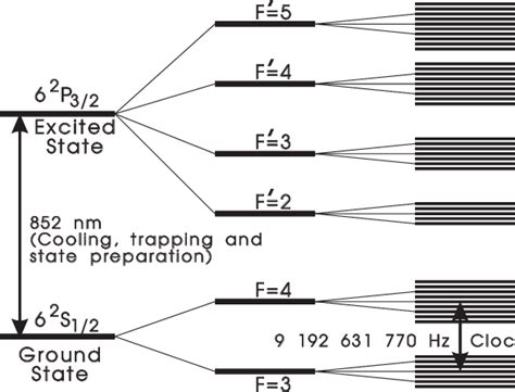 Cesium-133 atom hyperfine transition states - Bernard. J et. al. - Laser-cooled atoms and ions in precision time and frequency standards. [1])
Time
Given that SI units define time based on the cesium-133 atom its no suprise that we can use a cesium clock to provide an absolute time reference. Using such a clock we can count the number of oscillations until it matches what should match exactly one second and measure how much oscillations the device under test (DuT) deviates from this. Usually the DuT provides a 10 MHz signal and our cesium clock signal is divided down to this common reference frequency. Even further, parts of an oscillations or the phase between oscillation periods can also be measured. Lastly, this difference can be sampled multiple times per second as opposed to just once. The result is the drift of an oscillator over time. Using statistical methods this drift can then be used to quantify the stability of the oscillator as will be described later.
These cesium clocks are prohibitively expensive however, so a cheaper solution is needed. Luckily, each GPS satellite contains one such a cesium clock. The signals of these GPS satellites and the underlying protocol thus allows us to reconstruct a time signal based on data from all currently received GPS satellites.
GPS
This reconstructed time signal is provided as square wave oscillating once per second (1 Hz), this signal is called Pulse Per Second (PPS). The short term stability behavior in terms of phase noise and harmonics of this signal is very poor, much worse than even the worst crystal oscillator. However, the long term behavior of this signal, over tens of minutes is better than even an Oven Controlled Crystal Oscillator (OCXO). If only there is a way to combine the short term behavior of an OCXO with the long term behavior of a GPS PPS square wave!
GPSDO
This is precisely the task of a GPS disciplined oscillator, these devices integrate two different clock signals adjusting the output clock of one using the other as reference clock to modulate these adjustments. The result is a self-stabilizing feedback loop for which the characteristics of one clock signal can be made dominant after a given period of time. This integration time, after which one of the two clock signals becomes dominant can be controlled. This time is chosen to match the precise transition point where the characteristics of one clock become superior over the other.
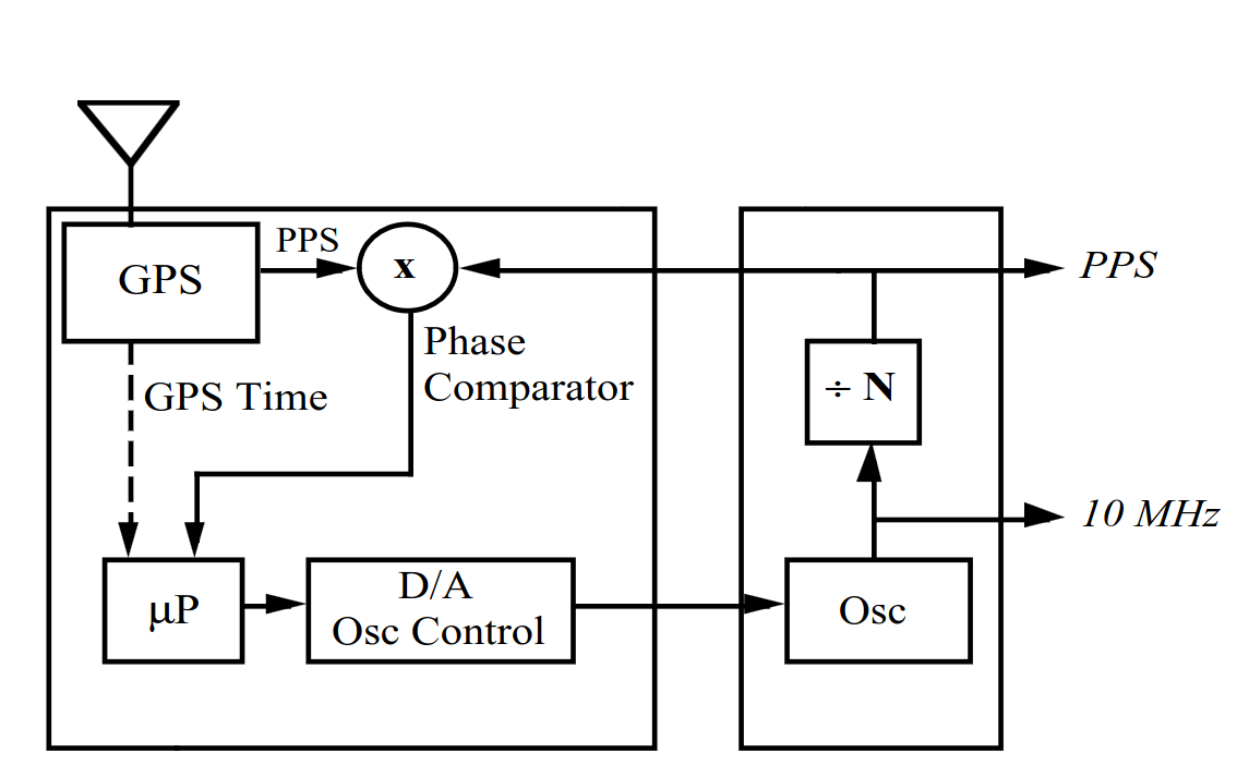 Block diagram of phase comparator controlled GPSDO
This works because all OCXOs there reference voltage can be adjusted. This adjustment voltage kan be derived from a phase comparator, specifically a phase locked loop (PLL). With a long intergration time this adjustment voltage is adjusted slowly ensuring it takes a long time before the GPS PPS signal becomes dominant.
Characteristics
The critical setting within this system becomes the integration time. This needs to be set as such that it occurs just on the transition where the characteristics of one clock surpass the other. This requires us to understand these characteristics in detail, primarily these are phase noise and frequency stability. This phase noise can be measured easily directly at the output of the GPSDO. This will be the output of the OCXO and can be done on a spectrum analyzer using a bode plot. In such a bode plot the power density of a 1 Hertz bandwidth of the spectrum is measured relative to the power at the carrier. We repeat these measurements for specific distances from the carrier and express it in terms of dBc/Hz with lower values being better.
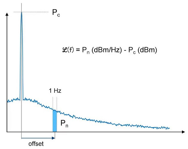 Bode plot describing how dBc/Hz is measured
The other characteristic, frequency stability, is measured using repeated phase differences between two clock signals. This measurement is a lot less intuitive and requires the use of statistics. This statististical analysis differentiates if individual measurement points influence the short term or long term frequency stability.
Allan deviation (ADEV)
Luckily these statistical methods have been published long ago and are well standardized. One of these methods is called Allan Deviation (ADEV). This mathematical method modulates a selection factor $m$ with reference to the measurement interval $t$ (the sample interval in seconds used during collection the measurements). By increasing the factor $m$ we can select measurement points that are multiples of this measurement interval $t$. In the base case $m=t$ and each sample will be accounted in the calculation. Using $m = t*2$ the sample selection will switch between selected and unselected between each sample. Given an one second sampling interval and $m = 10$ would result in a sample selection of sample $10, 20, 30$ etc from our sample set. The remainder of the formula is based on variance and standard deviation, as a reminder to those bright college days, this is the summation of each sample of the sample set squared en multiplied by $1\div{(N-1)}$ where $N$ denotes the number of selected samples.
Overlapping Allan Deviation (OADEV)
In reality this basic formula for ADEV is rarely used and Overlapping Allan Deviation (OADEV) is used or even Theo1 instead. This formula has the advantage of reusing measurement samples more often for different values of factor $m$. The entire formula for OADEV is shown below.
$$\sigma^2_y=\frac{1}{2(N-2m)\tau^2} \sum _{i=1}^{N-2m} [x _{i+2m} -2x _{i+m} + x _{i}]^2$$
To be able to reuse measurement samples OADEV selects not one but three samples per point in the summation as denoted by $[ x _{i+2m} -2x _{i+m} + x _{i} ]$. The subscription of $x$ denotes the index of the sample being selected from the sample set where $x _{1}$ denotes the first element.
The results of an OADEV computation as performed by the TimeLab [2] program are shown below. With these results lower values represent better results (higher stability).
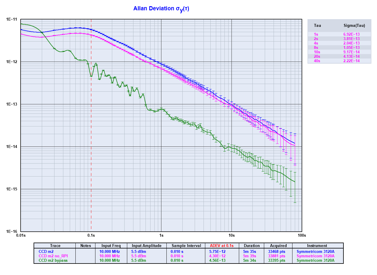 Results of OADEV calculations in TimeLab
In practice
Collecting measurement data to perform these frequency stability measurements requires access to a reference clock that is more stable then the clock you are trying to measure. The results is that while it is realitively cheap to build a GPSDO using off-the-shelf hardware, validating it and adjusting the cross over point for integrating the clocks signals is difficult.
Potentially the least commercially demanding solution that can provide adequate results is the use of refurbished rubidium clock oscillators from ebay.com or aliexpres.com.
These rubidium clock oscillators can be used as a reference clock on the NanoVNA H4 [3]. This NanoVNA H4 is a handheld Vector Network Analyzer (VNA) for which the TinyFPA [3] firmware was written by the community. This NanoVNA H4 can be readily bought online but through platforms like aliexpress or ebay defects can occur due to cheap reproductions so official resellers are advised.
With the TinyPFA firmware the NanoVNA H4 becomes a phase frequency analyzer that is able to provide measurement data that can be analyzed by TimeLab directly using serial over USB.
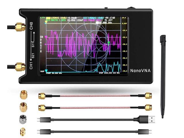 NanoVNA H4 and typical accessories
This setup will be used to analyze and iteratively improve the design of a GPSDO using the ADF4001 phase locked loop. The design as well as the measurement setup will hopefully be described soon in subsequent articles.
73,
Corne Lukken (PD3SU)