Hameg hm1005 analog oscilloscope repair
A systematic approach to electronics repair
Introduction
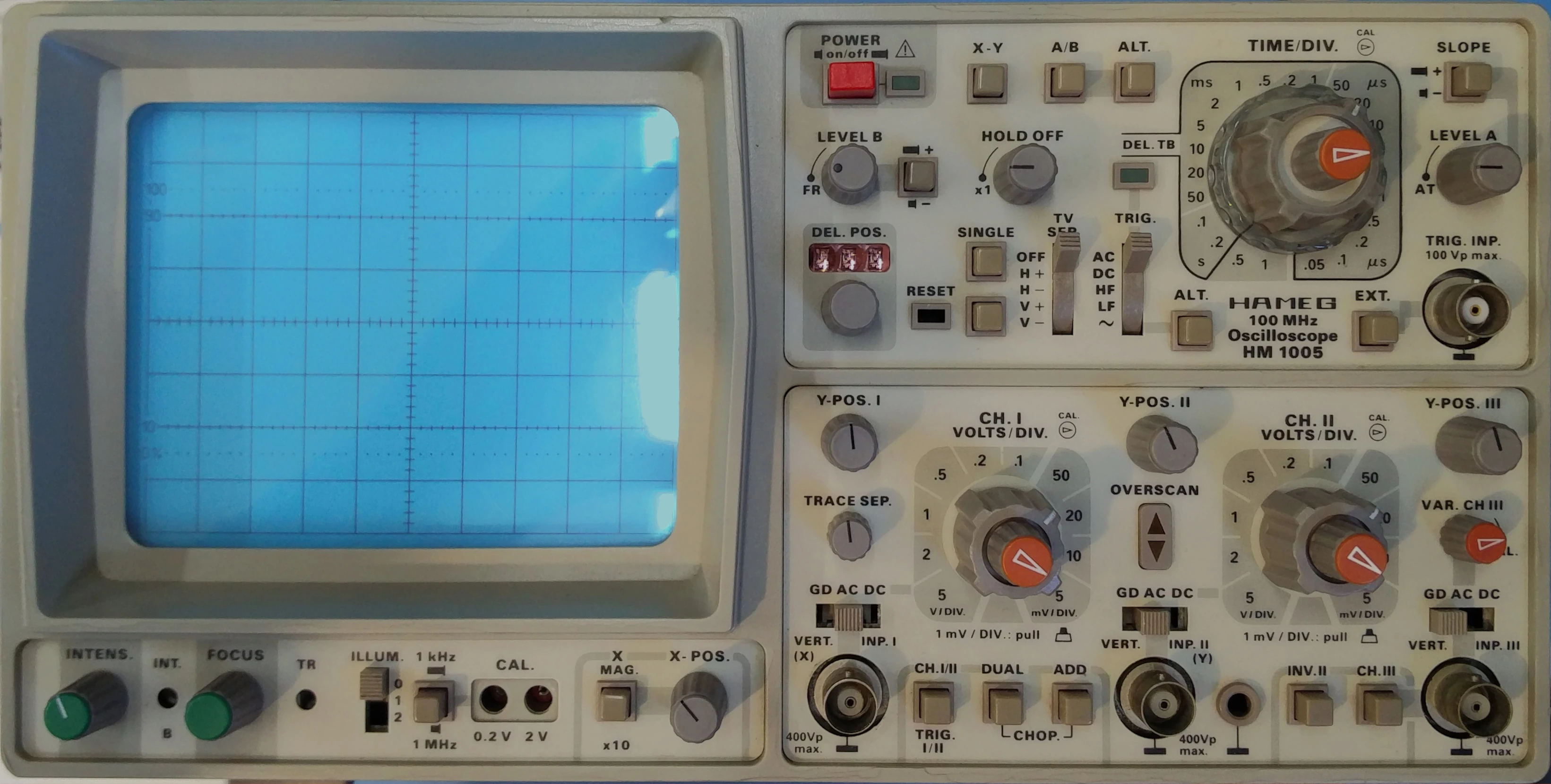
Years ago I received an Hameg HM1005 analog oscilloscope. These scopes, much like any Hameg really, is easily recognizable by its easy to understand user interface. Unique to this Hameg scope is its combination of analog and digital features. Most prominently its three 100MHz bandwidth inputs, x times y mode and 10x horizontal zoom. Its one and only feature is a digital adjustment between 0 and 999 steps for the delayed timebase.
During its acquisition I was already told that several problems plagued the scope from operating correctly. This must have been roughly 5 years ago already and the scope has been in working order for some time. I have documented this and other reparations on electronics in case I need to revisit them. But how do you take on such a repair in a careful and systematic manner? This is the process I’d like to share in detail.
Steps to a successful repair
Honestly, there are dozens of ways to approach an electronics repair and this is not necessarily the best one. However, I will write as if this is the only approach to keep the rest of the story as brief as possible. In this approach we will cover 6 individual steps that should be executed in order. Normally, there would also be a re-calibration step but this turned out to be unnecessary for this repair.
Very brief, these steps are in order fault analysis, disassembly, repair, verification and assembly. Normally re-calibration would be performed after verification.
Step 1: fault analysis
In this first step we determine the problems the device is having and every condition in which this problem appears. Take care to note down these conditions and the problems either using a table on a piece of paper or in a program like excel. Twiddle and pull knobs and buttons as loose contact is a very common problem. Lastly, be patient several problems can take a long time to appear. Sometimes intermittent problems are caused by thermal stress or overheating, a cheap infrared thermal camera can help with this greatly.
Step 2: disassembly
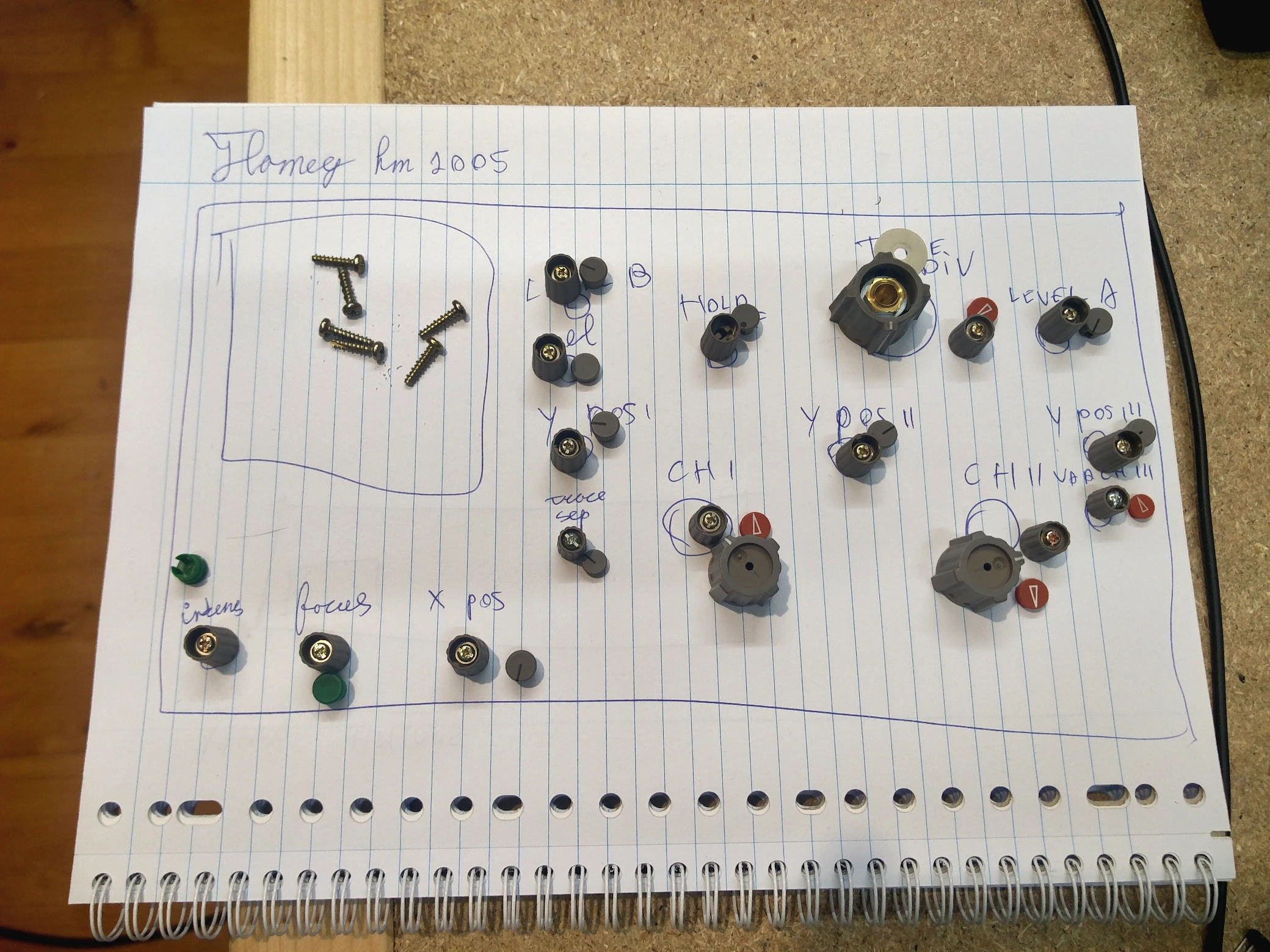
Secondly, during disassembly we carefully remove the exterior of the device but ensure it remains in a functional state. Sometimes cables might be of insufficient length in which case they should be extended. While extending cable that carry high frequency signals extra care is needed. Drawings should be made as an overlay of the front, back and other panels such that screws and parts can be marked on these drawings. These drawings will serve as a map during re-assembly. Loose parts can be taped down using scotch tape. More involved or intricate steps of the disassembly should be documented in a step by step guide. Lastly, reference the user and service manuals if possible.
Step 3: diagnosis
In the third step we finally start to use our fault analysis to identify the root cause of our problems. It is best to start this process with common fault analysis just because these are so predominant in electronics repair. These checks should include, checking voltage rails, refitting cables and connectors and checking fuses. If these checks proof insufficient a deeper analysis is needed. It is best to have schematics of boards available as reference. If these are entirely unavailable it is best to reconstruct suspected parts of the circuit in a reverse engineering process. This reverse engineering process can be performed by measuring resistance between points on the circuit. When it becomes difficult to reason about signal and current flow in small parts of the circuit a tool such as circuitjs can be used to visualize them. More advanced simulation is also available through spice programs. More recently kicad has also gained support for circuit simulation
Step 4: Repair
Finally, once the problem has been found the necessary adjustments can be made or parts replaced. When changing adjustable resistors or capacitors it is best to always first measure there initial value and document it. Similarly, if a component is to be replaced because it is highly out of spec note down the measured value.
Step 5: Verification
Fifth, with the problem supposedly solved we can begin the process of verifying the repair. Several actions are key to this step. These include, power cycling the device several times, letting it warm up and cool down and lifting the device and shaking it. Take into account the conditions that triggered the fault before especially executing these a few times. Use your intuition during this step, given the conditions in which you encountered faults, what could be potential further triggers? It is best to be thorough in this step and dissuade any self assurances of the current repair. Depending on the fault and the repair it might be necessary to switch between step three and four several times.
Step 6: Re-assembly
Finally, in the last step, the device is re-assembled using the documentation created earlier and it can be put back in working order. It is recommended to document the entire repair process even including pictures in case the fault returns again. The likelihood of this depends highly on the type of fault.
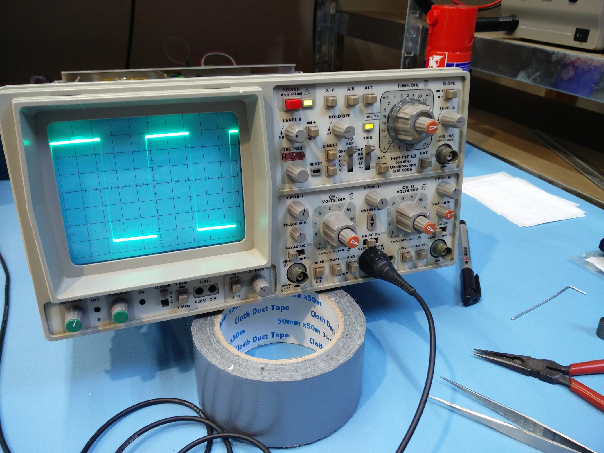
Repairing the Hameg hm1005 analog oscilloscope
With these clear steps in mind we can perform the actual repair on the Hameg oscilloscope. This diagnosis starts by turning it on making it clear that no signal is shown on the display. However, the underscan indicator lights up suggesting the signal is below the display line. When the vertical position is adjusted it needs to be turned almost the entire way for the signal to even appear on screen. Turning it the entire way leaves it roughly half way across the screen. This is a strong indicator towards the cause of the problem. Immediately a thought process starts as to what parts of the device relate to drawing the trace on the screen. For me, this indicates a potential problem with the power supply, specifically the section feeding the vertical power amplifier. Or perhaps the vertical power amplifier itself. The reason the final power amplifier is a stronger suspect then any intermediate stage is because the final power amplifier will dissipate the most power. This makes it undergo the most mechanical and thermal stress which contributes highly to failure rates.
Understanding the failure
But why would the failure of such a vertical amplifier lead to the signal only going up half way on the screen? This type of reasoning relies on intuition but a lot can be determined from analyzing schematics as well. Most if not all vertical amplifiers in devices such as oscilloscope utilize differential amplifiers. These types of amplifiers are built by having two identical (symmetric) amplifier chains. If either the top or bottom half of this chain is not working we would expect the signal to only go halfway (or only start halfway). I also suspected that it might be that the amplifier was not getting the appropriate voltage. We should also employ steps to validate our intuition, cross referencing schematics. In this case we can use multiple input channels to verify the problem persists across all of them. When analyzing the schematic it was clear that the oscilloscope was indeed using differential signaling and amplifiers as observed from the single ended to differential conversion in the analog frontend.
Differential signaling has a number of advantages such a noise immunity through common mode rejection. Especially, when this conversion is performed as early as possible. As a result the Hameg HM 1005 is relatively quiet even at 1 mv per division. Even though the high frequency analog signal has to move across a very cheap sliding switch (oef). Given the partial functionality we can continue with further investigating any other issues. Among these are several potentiometers that are very tight or with bad contacts. Especially the contacts for Volts per division behave particularly poorly between the 20mV and the 50mV range.
In short the fault analysis detected 5 individual problems with the first and foremost being the most substantial.
- Vertical deflection does move past first half of screen.
- Intensity of screen is poorly adjustable en varies spontaneously.
- Trigger level (A) varies spontaneously.
- Sensitivity (Volts per division) of second channel switches poorly.
- Sensitivity of first channel is almost completely stuck.
Disassembly
The five problems conclude our fault analysis we can now continue with the disassembly. Luckily, this is relatively straight forward for this Hameg oscilloscope. 2 screws hold the case at the back afterwards it can glide of. Everything internally is secured to a ridged internal frame. This frame also holds the front panel using 5 screws. The indicators have to be removed to remove the front panel. This results in having to re-calibrate the indicator dials which we will deal with later. It is best to store dials on a drawn layout that represents the front panel.
With every panel easily removable and the entire boards connected to a rigid internal frame. In this case there is no need to extend any cables between board to board connections to improve access. Normally, extending cables or cards so they can be accessed while the device is operating is a common part in my repair procedure. Having the device operating and accessible aids in the process as it simplifies measuring signals tremendously.
Common checks
During these initial repair steps I’d recommend to perform checks for common faults these include:
- Supply voltages
- Capacitor leakage current
- Connector seating
The monitoring of supply voltages is ideally done under load this helps identify potential shorts or supplies that can not supply enough current. Typically labels can be found on the board marked with test points and voltages. If not on the board themselves potential test points are often easily found from the schematics.
Leakage current is best measured out of circuit. A capacitor can easily be taken out of
circuits by removing on of the two legs from the board temporarily. The primary suspects
are large electrolytic or very old paper capacitors. The leakage current can be measured
by supplying a voltage through a current limiting resistor. The leakage current is then
measured from the voltage drop across the resistor. For this it is best to use resistors
that are multiple of 10s. A resistance of 1k would give a drop of 1 volt per ma (10k would
give 1 volt per 100 uA). Take into account that the voltage drop is also the burden
voltage and it will influence the measurement. As a rule of thumb try to use a resistor
value that keeps the voltage drop below 1 volt. The leakage current for electrolytic
capacitors should be less the 0.01*C*V. Where C is in uF en V is in volts. The leakage
of most other capacitor types should be on the order of 10 to 1 uA. For example a 10.000
uF 40 volt electrolytic capacitor should have a leakage current smaller then 4 mA.
Lastly connectors should be firmly wiggled and re seated by removing and putting them back. Also check pins for crust or other degradation. The pins can be softly scratched to remove these contaminants if desired. Optionally, a resistance measurement or continuity tester can be used to identify if connections are intermittent and make solid connection.
Diagnosis
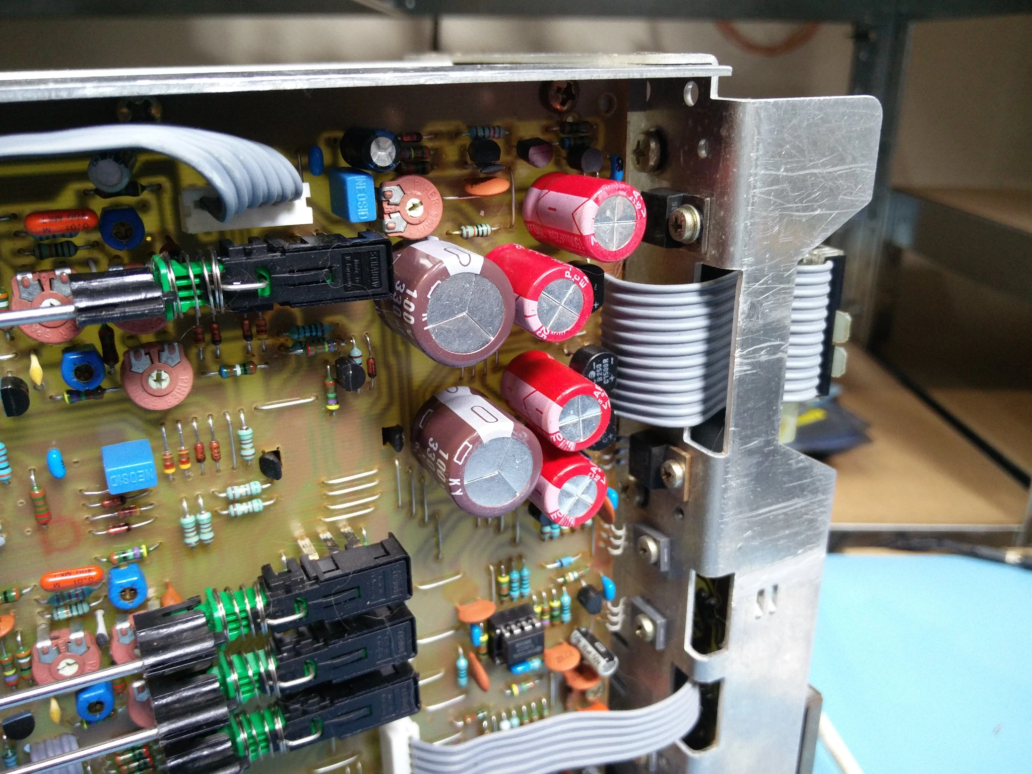
By utilizing these checks I determined that at least some of the capacitors from the main power supply section needed to be replaced. To ensure prolonged live I replaced the entire capacitor section. Given that this is only 6 capacitors in total the cost is relatively minor. For good measure I bought low Equivalent Series Resistance (ESR) capacitors from a name brand like Rubycon.
These capacitors replacement did not resolve the vertical deflection issues hinting us further at problems with the vertical amplifier. For this I identified 6 stages of final amplification from the schematic. The reason I start diagnosing the final amplifier board first is because it dissipates the most power making it undergo the most thermal stress which aggravates failure. Using the symmetric design of such a differential amplifier I can verify the output at each stage by verifying the drive level is identical at both sides. To clarify, I turn the vertical position all the way down for the bottom half and all the way up for the top half. The drive level will likely be negative for the bottom half but the voltage should still roughly match.
I followed the drive level for each stage and was met with a lack of output at the final stage. When I tried to use the schematic for referencing this time it seemed none of the transistors in the amplifier chain matched. It is common for these types of device to undergo multiple revisions during their production. Unfortunately only one revision is typical available as online download and it is not easy to identify which version is made available. I aim to improve this over at our museum https://museum.dantalion.nl/documents
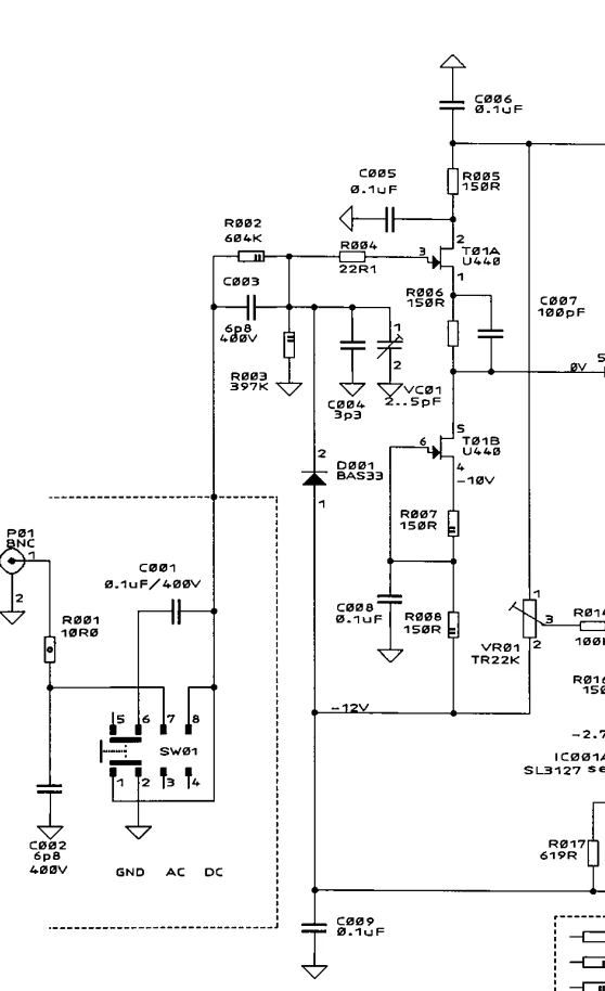
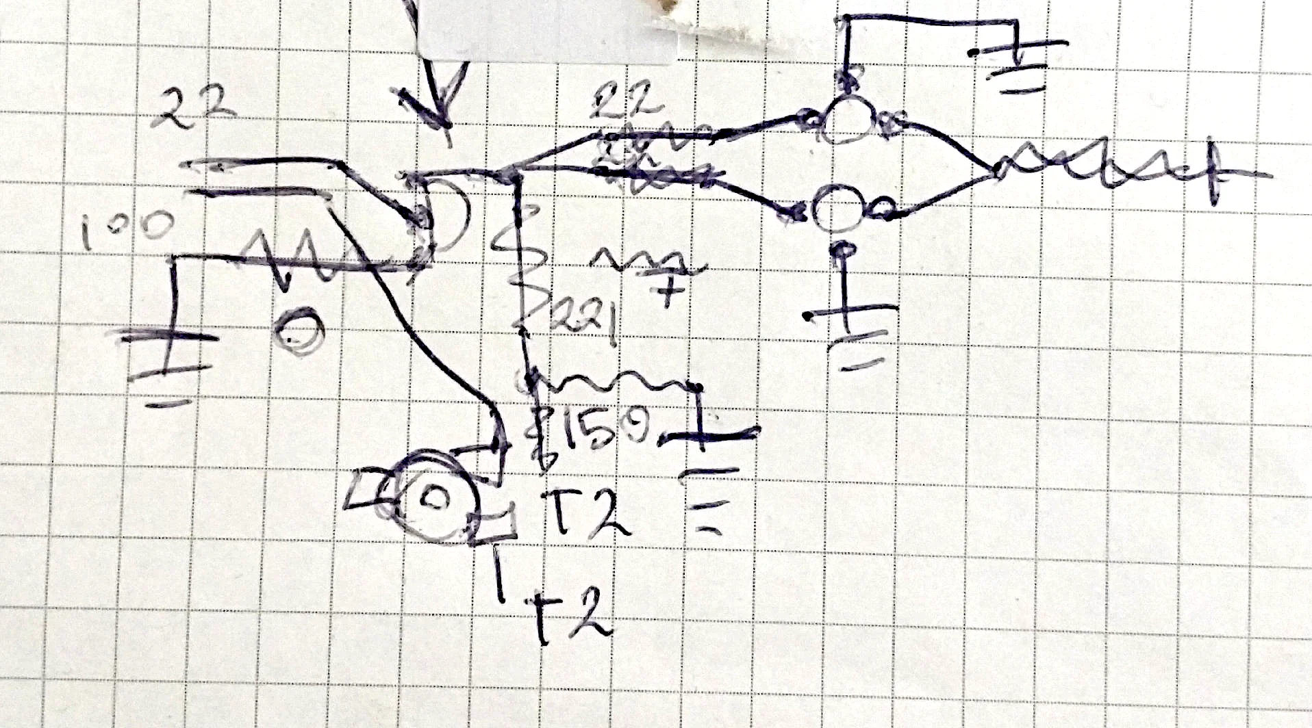
Given that the schematic did not match the vertical amplifier board a little tracing was in order to reconstruct the essential parts. This helps determining the connections at the underside of the board and how they attached to several components, including the transistor without a drive level. Looking at it now years later it makes little sense to me but I remember that it aided me in finding the connection.
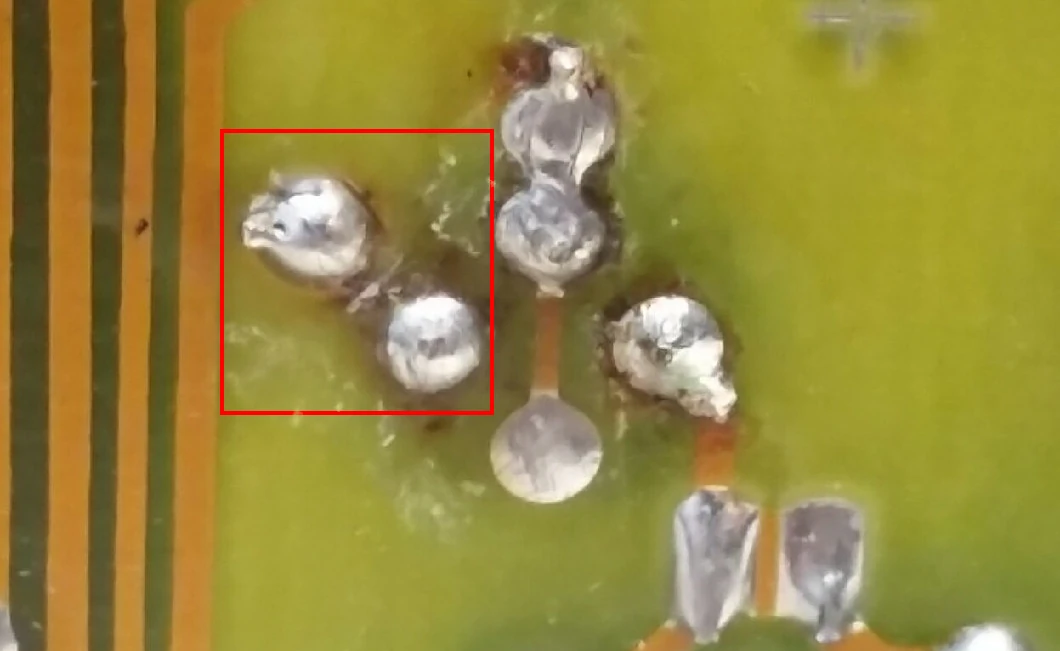
When using this schematic to trace the bottom of the PCB board to the top it was not immediately clear why no drive signal appeared on the output. It took several minutes of closely looking before I noticed the trace had completely burned out. A continuity test proved there was indeed no connection between the top left leg and center pad as marked in red in the next image.
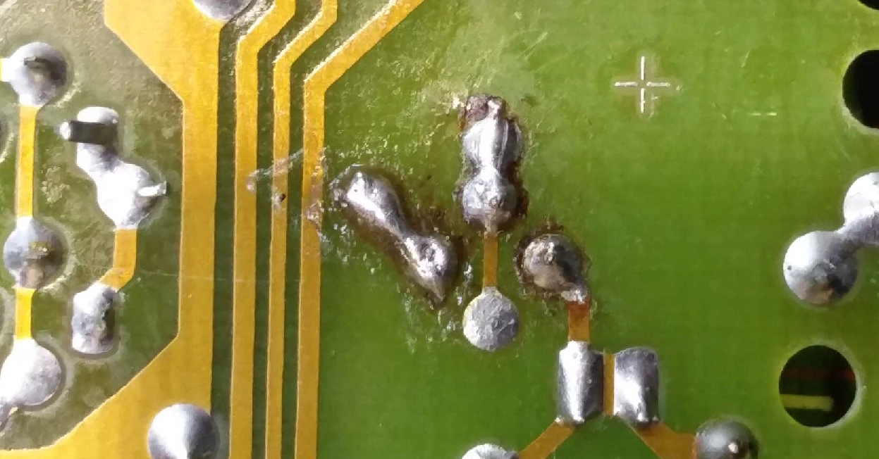
The length between the traces was short enough that solder could be used directly to bridge it. The final repair is shown in the image below. We can verify that this resolved the vertical deflection issue because we have ensured the device can be used while disassembled for repair.
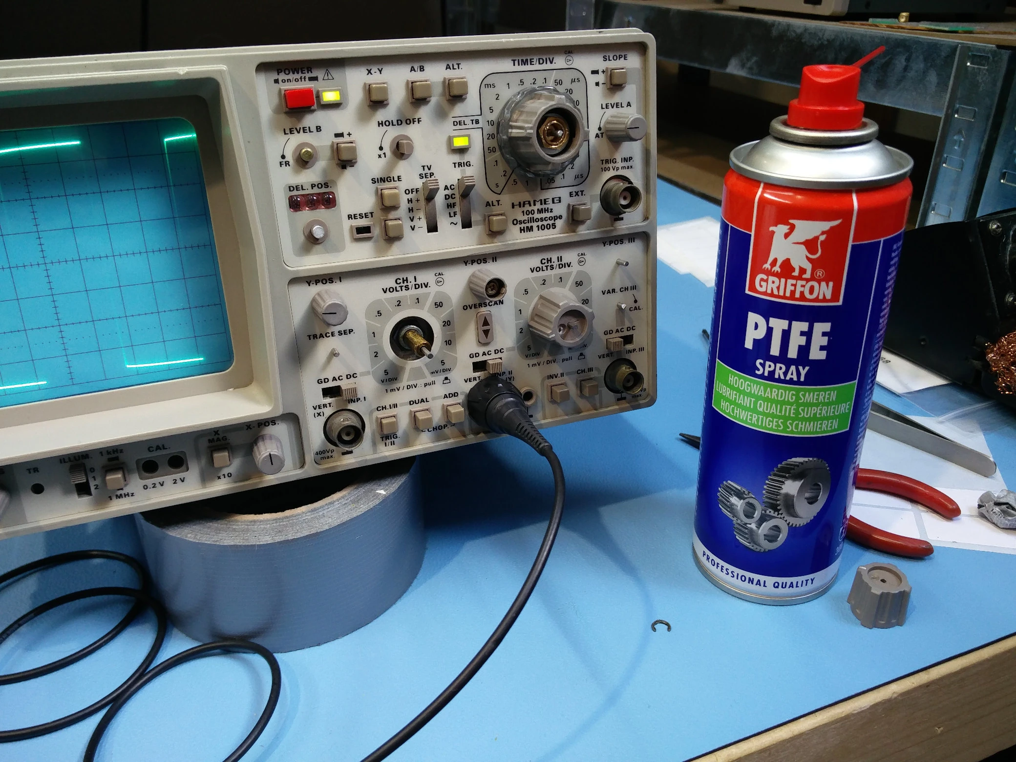
With the electrical defects dealt with the focus remains on the knobs and buttons that are misbehaving. I repaired most of them, especially smaller ones by repeatedly moving them from left to right. This worked for the trigger level and screen intensity. For bigger potentiometers, especially those with safety pins, I recommend to use PTFE spray. To do this simply remove the safety pin and spray PTFE spray into the hole. Afterwards let it soak for a minute and then start moving it from left to right. This can not only repair intermittent behavior but also unstuck ceased potentiometers. The PTFE lubricant is soft enough where it won’t damage the axle or the carbon trace inside.
With the PTFE spray the two potentiometers controlling the volts / division on both channels came free quite quickly. With this the functionality has been restored.
The final step is to re-align the indicators of the front panel for this two separate approaches are needed. Most indicators should be aligned such that the arrows travels equal amount to the left and right. Depending on the age and built techniques of the device aiming the indicator straight up might be sufficient to achieve this. Other indicators should be aligned based on their impact on operation. For instance, horizontal and vertical position. These controls are best aligned such that the centering on the indicator achieves centering on the screen of the device.
It should be noted that it might not always be possible to achieve centering for any control. With the Hameg the horizontal axis gets a substantial offset when x times y mode is enabled. The decision has to be made to center the indicator for regular use or for use in x times y. Depending on the device and calibration procedure it might be possible to reduce or eliminate these offsets with internal trimmers.
Summary
We got lucky with this repair having the primary failure in section that is symmetrical. Even more so, the repair did not require a single part to be replaced. Even calibration was not really required. For now the Hameg HM1005 is fully functional again with smooth potentiometers and solidly switching knobs and buttons. A happy device with a happy owner.