RISC-V RV32I assembly with Ripes simulator
From extension, instructions to stack frames and function calls
Assembly is the closest resembling programming language to pure machine code instructions. The available instructions depend on the architecture and even supported extensions. In this tutorial the available instructions will be limited to the most basic set of RISC-V instructions. This set of instructions is denoted as RV32I meaning that it entails RISC-V 32 bit basic integer instructions. Not only will this limited set simplify the explanation and subsequently aid the understanding. More important, the Ripes simulator only supports RV32I and RV32M extensions. Here the RV32M identifies that multiplication instructions are also available to be performed on integers. Before continuing with the installation of Ripes lets briefly consider the available extensions for RISC-V today. Take into account that these extensions are being actively worked on, new extensions get drafted and existing extensions get updated.
Extension Overview [1]
- A – Atomic instructions
- B – Bit manipulation instructions
- C – Compressed instructions
- D – Double-precision floating-point instructions.
- E – Embedded applications, resource constrained subset
- F – Single-precision floating-point instructions
-
G – General (I + M + A + F + D)
- I – Integer instructions
- J – Dynamically translated languages
- L – Decimal floating-point instructions
- M – Integer multiplication and division instructions
- N – User-level interrupt instructions
- T – Transactional memory instructions
- V – Vector operations instructions
These extensions are the instruction extensions as defined for the user-level ISA specification 2.2 [2]. In addition to this specification there are also the unprivileged ISA specification [3], privileged ISA Specification [4] and a debug specification [5]. All these extensions and specifications might seem excessive but they allow for great flexibility. This flexibility will allow to create low power tiny microprocessors with only integer arithmetic. As well as full desktop processors with vector extensions. Furthermore, even special designed processors such as secure processors with separate program and data memory are possible.
Understanding Basic Assembly
In a nutshell, assembly instructions perform read, write or arithmeti operations on either registers or memory addresses. These registers are locations inside the processors of a specific length to which can be read from or written to. Typically the available registers depends on the extensions implemented by the processor. One can think of registers as short term memory. Places to store temporary information so it can be written down (to memory) later. For the RV32I extensions there will be 32 individual 32bit long registers labeled x0 to x31. For Convenience many of these registers have specific names which indicates their purpose. In reality this is just for semantics and one is free to use any register for their desired purpose. Compilers, however, operate under the assumption that they can use certain registers consistently. To correctly identify return types for example.
First Instruction
The first instruction to consider is called addi this is short for add immediate. Just like functions these instructions take arguments where in the case of addi three arguments are expected. First is the register to store the immediate into, second is the first integer and third is the second integer. The addition of the first and second integer will be stored in the specified register. Consider the example shown below where the addition of 0 + 5 is stored in the a0 (x11) register.
addi a0, zero, 5
Since an integer is a 32bit value it can only represent a limited range of discrete numbers. When adding to sufficiently large integers the addition can no longer represent the entire discrete number and it overflows. In other ISAs such as X86 such an overflow will set a flag in specific register. Such flags allow the program to detect that an overflow has occurred. However, in RISC-V it is up to the individual implementation how to handle such overflows, divide by zero, carries and other arithmetic events that might occur when executing instructions. Of course just adding, subtracting or multiplying integers is only going to get us so far. Most programs rely on conditions where a certain set of instructions is only executed if the condition holds. With subsequent assembly instructions the equivalent pseudocode as it could be interrupted in a higher level language such as Java or C is shown beside it.
Conditional Branches / Jumps
blt a0, a1, .conditional # if(a0 < a1) goto conditional;
Above is the branch less than instruction which jumps to the specified label
if the first parameter is less than the second parameter. The third argument is
the label to jump to. Labels are declared in assembly programs with specific
names so they can be jumped back to later. Efficient assembly code uses small
general purpose snippets of labeled code which can be reused many times. This
effectively reduces the size of the program although it can sometimes be at the
cost of performance. In addition to conditional jump instructions or branch
instructions are they are called in RISC-V. There is also the unconditional
jump. This instruction will always jump to the specified label unconditionally
and in RISC-V it is denoted simply as j.
j .exit # goto exit;
Why labels are more comparable to goto than a function call is because of the assembly instruction call which performs the actual call to functions. Calls are more involved than jumps requiring the correct setup of stack frames and dealing with return data. For now, it is important to know that it exists but basic loops are covered first before dealing with proper functions and their corresponding stack frames.
Storing and Loading from Memory
The final instructions to consider before the first program can be analyzed are the load and store instructions. Known as lw and sw in RISC-V these mean load word and store word respectivelu. Read the following examples below but do not worry if it is not immediately clear how they operate.
sw a0, 0(sp) # store the contents of a0 in the address of sp
lw a0, 0(sp) # load the contents of the address sp into register a0
An important property of a register is that it can be used to store a address in memory. This is known as an reference, subsequently with such a reference we can point to specific addresses in memory. The lw and sw allow to store and load information from registers into these memory references. The example below will show the importance of reading and writing to memory although arguably the most complicated instruction shown yet.
addi sp, zero, 0xff # set the sp register to 0xff in hexadecimal
sw   a0, 0(sp) # use the value 0xff from sp as an memory address to store a0
addi, a0, zero, zero # set register a0 to 0 losing its previous value
lw  a0, 0(sp) # use the value 0xff from sp as memory address to restore a0
This covers all assembly instructions that will subsequently be used in the Ripes simulator. When using this simulator the execution pipeline and results on registers or memory locations can be viewed graphically.
Installing Ripes
There are multiple methods to install Ripes for most operating systems. By far the simplest method is to download the release from Github. The information in this post will be based on Ripes version 1.0.3 [6].
All the three executables the .exe, app and AppImage can be executed directly. As a result, the download location is up for the end user to decide and afterwards the file can be removed if desired. OSX users are entrusted to be familiar with allowing third party executables to be allowed to run. Similarly, Linux users are expected to know how to set file permissions to make files executable. Now start Ripes and lets get started.
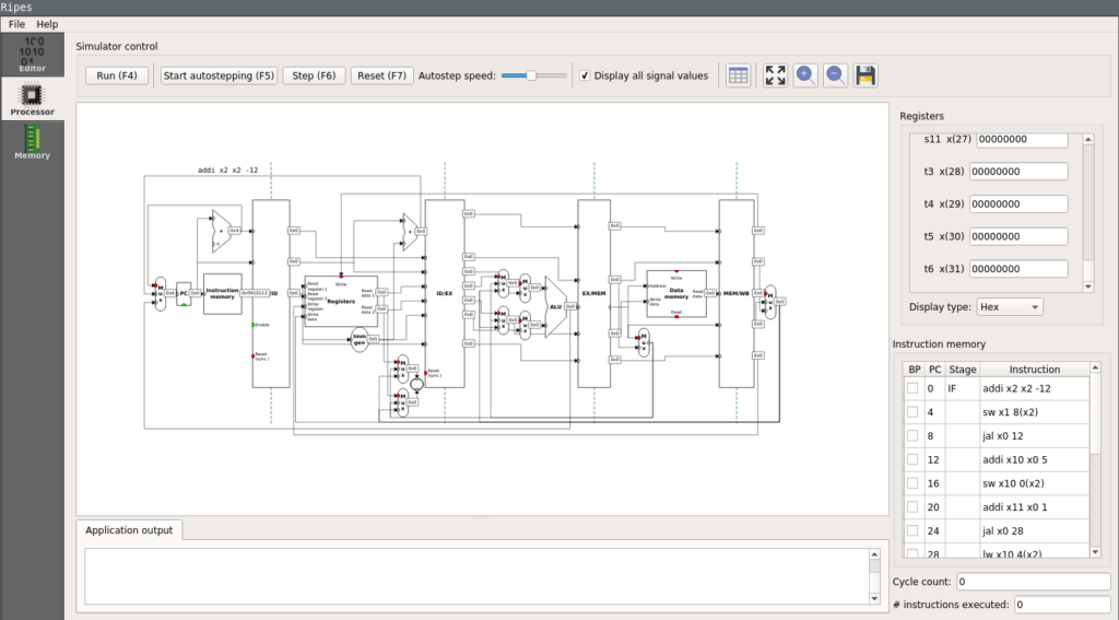 |
| Ripes simulator processor view |
The First Basic Loop
The first example will entail a basic for loop that will start at 5 and decrement until smaller than 0. At first a minimal assembly representation of this will be covered. Slowly other important aspects that also need to be handled in assembly will be covered.
#pseudo code
for(int i = 5; i > 0; i--) {}

# assembly equivalent
addi a0, zero, 5
addi a1, zero, 1
j .loop

.loop:
    blt a0, a1, .exit_loop
    addi a0, a0, -1
    j .loop

.exit_loop:
    ...
Before starting to announce improvements lets analyze the assembly shown above.
Initially the value 5 is put into the a0 register following 1 being put into
a1. Now a unconditional jump is performed to enter .loop. Inside the loop
(a0 < a1) is evaluated and if true a jump to .exit_loop is performed.
Obviously 5 is not less than 1 so the execution continuous normally. Next a0
is decremented by one and the subsequent jump goes back to the start of the
loop. Now 4 is still not less than 1 but the looping pattern has become
apparent. When the value in a0 has become 0 it is less than 1 which is in the
a1 register and a jump to .exit_loop will be performed. Below the operation
of this simple loop is visually demonstrated step-by-step, of course it is
encouraged to perform this stepping in Ripes yourself.
Functions Calls and Stack Frames
Inevitably a program at some point becomes so significantly complex that it
would be impossible to keep an overview without functions. Even in assembly the
concept of functions is well know, however, in assembly a programmer needs to
perform various tasks to ensure a call executes correctly. Before the next two
assembly instructions call and ret can be properly introduced, some
registers their special purpose has to be described. Lets take a look at the
registers sp(x2), ra(x1), s0(x8). Here the labels are no longer of
significant value so they will be omitted in the future. It no longer matters
that a0 is label x11 for example. Here sp stand for stack pointer, ra
stands for return address and s0 or otherwise known as fp stands for
frame pointer. The basic purposes of these registers will be explained.
However, for a more thorough guide on register conventions one is advised to
read Harry H. Porter III his guide
[7]
starting on page 146.
Return address (ra)
The return address (ra) is used to return from a call back to where the program was executing instructions before the call. In other architectures such as X86 the return address is stored in main memory. Using registers instead allows the executions of calls to be performed much faster and with lower overhead However, the storing or the return address in main memory can only be avoided if the function makes no subsequent calls to other functions.
Stack pointer (sp)
The stack pointer (sp) reserves space for calls to store variables in main
memory. It must always be modified by multiples of 16 bytes and reserving space
must be done by decrementing it. This is very typical for most architectures
where variables on the stack and heap are directly opposite from one another.
This allows to effectively use the entirety of available memory without
variables on the stack overwriting variables on the heap. After the reserving
of space by decrementing sp it must be subsequently incremented again by the
same amount before returning from the call.
Frame pointer (a0, fp)
The frame pointer (fp) is not always needed with every call, furthermore, it is likely that most calls won’t need to use the frame pointer. The frame pointer is used to determine offsets for calls that create variables with dynamic sizes. Additionally, a frame pointer is needed when using a large amount local variables due to a limitation in RISC-V on the maximum size of relative offsets. The dynamic use of the frame pointer is outside the scope of this tutorial, however, the value will correctly be incremented and stored in examples.
Stack frames
Stack frames are sized in 16 bytes chunks, naturally, this makes the smallest
possible stack frame 16 bytes large. A stack frame is constructed by
decrementing the current value of sp and subsequently storing ra and fp in
main memory. The storing of ra and fp is done with a relative offset to
sp. Finally fp incremented by the size of the stack frame. When a stack
frame is destructed the original value of fp is restored from main memory.
Followed by restoring the value of ra. Finally, the value of sp is
incremented back up to its original value. Below is an example of the
construction and destruction of the most basic stack frame.
# construction
addi    sp, sp, -16
sw      ra, 12(sp)
sw      s0, 8(sp)
addi    s0, sp, 16
# destruction
lw      s0, 8(sp)
lw      ra, 12(sp)
addi    sp, sp, 16
Before putting this all together and introducing the call and ret
instructions. Consider the following stack frame that takes one argument and
returns this argument after performing an addition with itself. The argument
taken is a regular 32bit integer and all operations with this argument use the
a0 register. Upon careful inspection of the assembly instructions it can be
observed that many of the sw and lw instructions could be optimized away.
Partly this is the job of the compiler but also of the programmer. Writing
return num + num; would have removed almost all of the sw and lw
instructions shown below for example.
#pseudo code
int sum(int num) {
    num += num;
    return num;
}

# construction
addi    sp, sp, -16
sw      ra, 12(sp)
sw      s0, 8(sp)
addi    s0, sp, 16
# store first argument
sw      a0, -12(s0)
# addition of a0 + a0
lw      a0, -12(s0)
add     a0, a0, a0
sw      a0, -12(s0)
# destruction
# load first argument
lw      a0, -12(s0)
lw      s0, 8(sp)
lw      ra, 12(sp)
addi    sp, sp, 16
Function Calls
The fundamental understanding of critical registers as well as the stack frames
allows to define complete functions which can be called in assembly. The call
instruction is similar to the jump in that it will jump to a label, however, it
expects the subsequent instructions to properly construct and destruct a stack
frame. When the destruction of the stack frame is completed the ret
instruction should be called. This instruction will ensure that execution
continues from where the call was made. To demonstrate consider the same
example as previously but now with appropriate function calls.
int sum(int num) {
    num += num;
    return num;
}

int main(int argc, char** argv) {
    return sum(5);
}
From main the sum function is called with the integer value 5 as it’s first
argument. For simplicity, let’s show the resulting assembly without the
construction and destruction of the main stack frame. Instead focus on how
call and ret are used to jump to parts of the assembly code.
sum(int):
addi    sp, sp, -16
sw      ra, 12(sp)
sw      s0, 8(sp)
addi    s0, sp, 16
sw      a0, -12(s0)
lw      a0, -12(s0)
add     a0, a0, a0
sw      a0, -12(s0)
lw      a0, -12(s0)
lw      s0, 8(sp)
lw      ra, 12(sp)
addi    sp, sp, 16
ret

main:
...
addi    a0, zero, 5
call    sum(int)
...
ret
Before calling the sum function the literal 5 is stored in register a0. This
is because a0 is the first argument by convention. Now call will jump to the
sum(int): label and start executing instructions from there. In sum it can be
seen that a0 is assumed to contain the value for the first argument because of
the sw a0, -12(s0) instruction. Naturally, the following lw a0, -12(s0)
instruction is redundant and only placed by the compiler if the -O flag is set
to zero. The keen eyed might notice the compiler has still managed to sneak one
optimization into the assembly as the return value after the call to sum is
assumed to still be in a0 when the main calls ret.
Simulating Function Calls in Ripes
When observing the resulting assembly in Ripes the call and ret instructions
no longer exist. This is because these instructions are converted by the
assembler depending on the addressing mode
[8].
The most common mode is called PC-relative and this uses relative offsets from
the program counter pc current address. This special register is only accessible
through specific instructions as is shown later.
With the first call to sum the instruction is translated into two separate
instructions. These instructions are auipc x6, 0 and jalr x1, x6, 24.
Firstly let’s translate the registers to the names we have used throughout this
post, these now become auipc t1, 0 and jalr ra, t1, 24. Here auipc stores
the pc register in t1 with an additional offset of 0. The jalr instruction
jumps to t1 + 24 and stores this address + 4 in ra. The +4 is needed so that
upon returning the jalr instruction is not executed again. While the 24 is the
relative distance between the auipc instruction and the start of .sum:. The
special auipc register allows to store the current value of the program
counter pc in a general purpose register such as ra.
The ret calls are translated to jalr x0, x1, 0 since this will jump back to
the address stored in x1 / ra. The return value of jalr is stored in the
unchangeable x0 register since there is no desire to modify any registers upon
returning.
Although, it is important to understand that the call and ret instructions
are actually translated into separate instructions that differ per memory model.
The underlying instructions used to facilitate these instructions are typically
not shown in a disassembly or while assembling.
Compiler Optimizations
As a final note, an example of the incredible optimizations compilers are able
to generate is shown. The same c code where the sum of 5 is computed in a
function is used but now the compiler -O0 flag is changed to -O3.
sum(int):
  slli a0, a0, 1
  ret
main:
  addi a0, zero, 10
  ret
The compiler has managed to infer the computation the sum function is performing and optimize them away by moving 10 into a0 and returning. Meaning, it has completely optimized away any function calls, construction and destruction of any stack frames. However, it still left the label to the sum function and the operations it needs to perform. This is because the function could be referenced from other libraries and files that might want to call it. It should be noted that this optimization can only be performed because the value 5 is known at compile time. Should the value be retrieved as program argument this optimization would not have been possible.
The Next Steps
Keep a look out for subsequent blog posts on RISC-V where working with the Maix bit and accompanying JTAG debugger will be covered. And maybe consider donating so I can buy one of those SiFive processors as well.